


The 36 Slot Motor Winding Diagram You’ll Ever Need: A Comprehensive Guide
Electric motors are the workhorses of modern industry, powering everything from household appliances to heavy machinery. Understanding their internal workings, especially the intricate dance of motor windings, is crucial for anyone involved in motor repair, maintenance, or design. This article provides a comprehensive guide to 36-slot motor winding diagrams, a common configuration, equipping you with the knowledge to understand, troubleshoot, and potentially even rewind these essential components. Whether you’re a seasoned technician or a curious enthusiast, this guide will serve as your go-to resource.
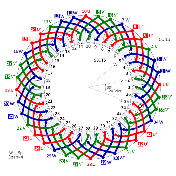
Understanding the Basics: What is a 36 Slot Motor?
Before diving into diagrams, it’s essential to grasp the fundamental concepts. A 36-slot motor refers to an electric motor with a stator (the stationary part) containing 36 individual slots. These slots house the insulated copper windings, which are strategically arranged to create rotating magnetic fields that drive the rotor (the rotating part). The number of slots influences the motor’s performance characteristics, including torque, speed, and efficiency. 36-slot motors are prevalent in various applications due to their balance of performance and ease of manufacture.
Decoding the Winding Diagram: Key Components and Terminology
Reading a motor winding diagram can seem daunting at first. However, understanding the key components and terminology will unlock its secrets. Here’s a breakdown:
- Slots: The individual spaces in the stator where the windings are placed.
- Coils: Groups of windings connected together. Each coil consists of one or more turns of wire.
- Coil Pitch: The distance between the sides of a coil, usually expressed in slots. This determines the motor’s electrical characteristics.
- Pole Pitch: The number of slots per pole. This is calculated as the total number of slots divided by the number of poles (e.g., 36 slots / 2 poles = 18 slots per pole).
- Winding Phase: The electrical connection of coils within a phase (typically three phases: A, B, and C) that creates the rotating magnetic field.
- Connections: The points where the winding leads connect to the motor terminals.
- Star (Y) Connection: Windings are connected to a common point, creating a star-shaped configuration.
- Delta (Δ) Connection: Windings are connected end-to-end, forming a closed loop.
- Pitch Factor: A factor that describes the ratio of the coil pitch to the pole pitch. This affects the induced voltage and the motor’s performance.
- Distribution Factor: A factor that describes the effect of distributing the coil groups across multiple slots. This affects the induced voltage and the motor’s performance.
Types of 36 Slot Winding Diagrams: Common Configurations
Different winding configurations result in different motor characteristics. Here are some common types of 36-slot winding diagrams:
- Single-Layer Winding: Simplest configuration, with one coil side in each slot.
- Double-Layer Winding: More common, with two coil sides in each slot. This improves the utilization of the stator slots and allows for more complex winding patterns.
- Lap Winding: Coils are connected in a “lap” fashion, resulting in a high current and low voltage.
- Wave Winding: Coils are connected in a “wave” fashion, resulting in a low current and high voltage.
- Concentrated Winding: All turns of a phase are concentrated in one slot. This is less common in 36-slot motors.
- Distributed Winding: Coils are distributed across multiple slots, providing a more sinusoidal magnetic field.
The specific winding configuration chosen depends on the motor’s desired performance characteristics, such as torque, speed, and efficiency.
Step-by-Step Guide: Interpreting a 36-Slot Winding Diagram
While specific diagrams vary, the following steps provide a general approach to interpreting a 36-slot motor winding diagram:
- Identify the Number of Poles: Determine the number of poles (e.g., 2, 4, 6) shown in the diagram. This will impact the motor’s speed.
- Determine the Phase Connection: Identify whether the winding is connected in Star (Y) or Delta (Δ). This affects the voltage and current characteristics.
- Locate the Coil Groups: Identify the coil groups for each phase (A, B, and C). The diagram will illustrate how the coils are connected.
- Trace the Windings: Follow the path of the windings from the starting point (e.g., U1) to the ending point (e.g., U2) for each phase.
- Note the Coil Pitch: Observe the distance between the coil sides, typically indicated by a number of slots.
- Understand Coil Connections: Pay attention to how the coils are connected within each phase, whether in series or parallel.
- Examine the Terminal Connections: Identify the points where the winding leads connect to the motor terminals (e.g., U1, V1, W1, U2, V2, W2).
Practical Applications: Troubleshooting and Rewinding
Understanding 36-slot winding diagrams is crucial for:
- Troubleshooting Motor Faults: Identifying open circuits, short circuits, and other winding defects.
- Rewinding a Burned-Out Motor: Accurately replicating the original winding configuration.
- Modifying Motor Characteristics: Potentially altering the winding configuration to change the motor’s performance (requires a deep understanding and is not recommended without expertise).
- Motor Design and Analysis: Understanding how winding parameters affect motor performance.
Resources and Tools: Where to Find Diagrams and Assistance
- Motor Data Books: Comprehensive resources often contain winding diagrams for various motor types.
- Online Databases: Websites specializing in motor information may offer downloadable diagrams.
- Motor Manufacturers: Contacting the manufacturer of the motor may provide the original winding diagram.
- Professional Motor Repair Services: For complex issues, consult experienced motor repair technicians.
- Motor Winding Software: Specialized software can assist in designing and analyzing motor windings.
Conclusion: Mastering the 36-Slot Motor Winding
Navigating the intricacies of 36-slot motor winding diagrams is a valuable skill for anyone working with electric motors. By understanding the fundamental principles, key terminology, and practical applications, you can confidently interpret these diagrams, troubleshoot motor issues, and even embark on rewinding projects. Armed with this knowledge and the resources provided, you’re well-equipped to tackle the challenges of motor maintenance and repair.
FAQs: Frequently Asked Questions
1. What is the difference between a Star (Y) and Delta (Δ) connection?
- A Star (Y) connection has windings connected to a common point, resulting in a higher voltage and lower current compared to a Delta connection. Delta connections have windings connected end-to-end, resulting in a lower voltage and higher current.
2. How do I determine the number of poles in a motor?
- The number of poles is typically indicated on the motor nameplate or can be determined by observing the winding diagram. The number of poles directly impacts the motor’s speed.
3. What tools are necessary for rewinding a motor?
- Tools include wire strippers, soldering iron, insulation materials, a winding machine (for larger motors), a VOM (volt-ohm-milliammeter), and a megohmmeter for insulation testing.
4. Can I change the winding configuration of a motor to alter its speed?
- Yes, but it’s a complex process requiring a thorough understanding of motor theory and potentially altering the coil pitch, number of turns, and other winding parameters. This is generally not recommended for beginners.
