The 12-Volt Wiring Diagram: The Only Guide You’ll Ever Need
Embarking on a 12-volt wiring project, whether it’s for your car, boat, RV, or a DIY electronics project, can seem daunting. Wires, terminals, fuses, and the potential for sparking – it’s enough to make anyone hesitate. However, with a clear understanding of 12-volt wiring diagrams, the process becomes significantly easier, safer, and more manageable. This comprehensive guide serves as your definitive resource, providing you with everything you need to understand, interpret, and utilize 12-volt wiring diagrams effectively. Forget wading through complicated manuals; this is the only guide you’ll ever need.
Understanding the Fundamentals of 12-Volt Wiring
Before diving into the diagrams, let’s establish a strong foundation. 12-volt systems are prevalent in many applications due to their balance of power and safety. Here’s a breakdown of the core components you’ll encounter:
- Power Source: Typically a battery (car battery, marine battery, etc.) providing the 12-volt DC (Direct Current) power.
- Wires: Conductors, usually copper, carrying the electrical current. Different wire gauges (thicknesses) handle varying current loads.
- Fuses: Protective devices that break the circuit if the current exceeds a safe level, preventing damage to components and potential fire hazards.
- Switches: Devices that open or close a circuit, controlling the flow of electricity to various components.
- Loads: The devices that consume the electrical power, such as lights, motors, and electronic components.
- Ground (Negative): The return path for the electrical current, often connected to the chassis or a dedicated ground wire.
- Positive (+): The wire carrying the power from the power source to the load.
Decoding a 12-Volt Wiring Diagram: The Visual Language of Electricity
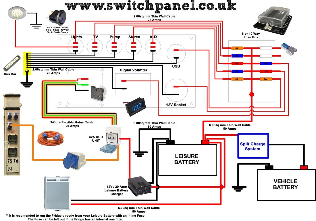
A 12-volt wiring diagram is essentially a blueprint for your electrical system. It’s a visual representation of how all the components are connected. Learning to read these diagrams is crucial for successful wiring projects. Here’s a breakdown of the common symbols and elements you’ll encounter:
- Wires: Represented by lines. Solid lines usually indicate the primary power lines, while dashed or dotted lines might indicate control circuits or less critical connections.
- Connectors: Depicted as circles or squares, showing where wires are joined.
- Fuses: Illustrated as rectangles, often with a number indicating the fuse amperage (e.g., 10A, 20A).
- Switches: Shown with a symbol indicating their type (e.g., SPST, SPDT, etc.). SPST (Single Pole, Single Throw) is a basic on/off switch.
- Loads: Represented by symbols specific to the component (e.g., a light bulb symbol for a light, a motor symbol for a motor).
- Ground: Indicated by a ground symbol (a series of horizontal lines decreasing in length).
- Battery: Often represented by two parallel lines, one longer than the other.
Types of 12-Volt Wiring Diagrams
Different types of diagrams serve different purposes:
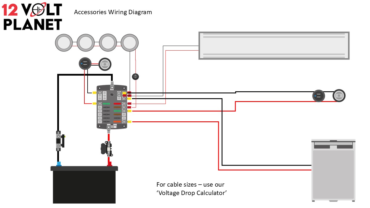
- Schematic Diagrams: These are the most common and detailed diagrams. They prioritize the electrical connections and often use standardized symbols. They are ideal for troubleshooting and understanding the circuit logic.
- Simplified Diagrams: These diagrams are easier to read for basic projects, focusing on the main components and their connections.
- Wiring Harness Diagrams: These diagrams are specific to pre-made wiring harnesses and show the connections within the harness itself.
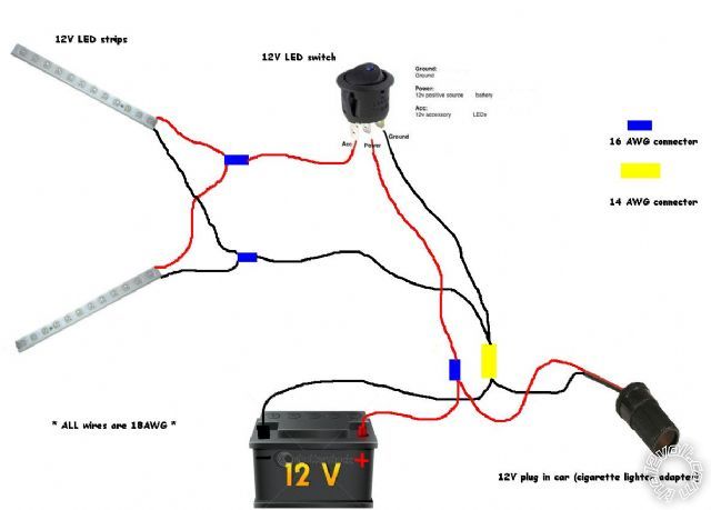
- Pictorial Diagrams: These diagrams use pictures of the components and wires to illustrate the connections. They are helpful for beginners but can be less detailed.
Essential Steps for Working with 12-Volt Wiring Diagrams
Following these steps will help you safely and effectively wire your project:
- Gather Your Materials: Acquire all the necessary components, including wires of the correct gauge, connectors, fuses, switches, and the load itself.
- Study the Diagram: Carefully examine the wiring diagram, paying attention to the connections, wire colors (if specified), and component symbols.
- Plan Your Route: Visualize the physical layout of the components and wires in your project. Plan the most efficient and safe routing of the wires.
- Cut and Strip Wires: Use wire strippers to carefully remove the insulation from the ends of the wires, exposing the conductors.
- Make Connections: Use crimp connectors, solder, or other appropriate methods to connect the wires to the components and terminals.
- Install Fuses: Insert the correct amperage fuses into the fuse holders.
- Double-Check Your Work: Before applying power, thoroughly inspect all connections to ensure they are secure and correct.
- Test the System: Apply power and test the operation of the components.
- Troubleshoot if Necessary: If the system doesn’t work, refer back to the diagram and check for loose connections, blown fuses, or incorrect wiring.
Wire Gauge and Current Capacity: Ensuring Safety and Performance
Choosing the correct wire gauge is critical for safety and performance. Using a wire that’s too small for the current load can lead to overheating, melted insulation, and potential fire hazards. Here’s a general guideline:
- Amperage: The amount of current the component draws. This is usually specified on the component itself.
- Wire Gauge (AWG): American Wire Gauge is the standard for wire sizes. Smaller AWG numbers indicate thicker wires (e.g., 10 AWG is thicker than 16 AWG).
- Length of Wire: Longer wire runs require larger wire gauges to minimize voltage drop.
Use a wire gauge chart to determine the appropriate wire size based on the amperage and length of the wire run. Consult a reputable source for these charts, as they can vary slightly depending on the application.
Troubleshooting Common 12-Volt Wiring Issues
Even with careful planning, problems can arise. Here are some common issues and how to address them:
- No Power:
- Check the battery voltage.
- Check the fuse (replace if blown).
- Check for loose connections.
- Ensure the switch is in the correct position.
- Component Not Working:
- Check the component itself for damage.
- Check the connections to the component.
- Verify the ground connection.
- Trace the circuit back to the power source, checking for breaks or shorts.
- Short Circuit:
- A short circuit occurs when the positive and negative wires come into contact, causing a large current flow.
- Immediately disconnect the power.
- Inspect the wiring for exposed wires or damaged insulation.
- Identify and repair the short circuit.
Conclusion: Mastering the Art of 12-Volt Wiring
Understanding and utilizing 12-volt wiring diagrams is essential for anyone working with electrical systems in cars, boats, RVs, or DIY projects. This guide has provided you with the foundational knowledge and practical steps you need to successfully navigate the world of 12-volt wiring. By following the guidelines, understanding the symbols, and taking the time to plan and execute your projects carefully, you can confidently create safe and reliable electrical systems. Remember to always prioritize safety, double-check your work, and consult with a professional if you are unsure about any aspect of the process. With practice and patience, you’ll become proficient in the art of 12-volt wiring.
Frequently Asked Questions (FAQs)
What is the difference between a schematic diagram and a wiring diagram? A schematic diagram focuses on the electrical connections and the logical flow of the circuit, using standardized symbols. A wiring diagram may show the physical layout of the components, including their location within a vehicle or system. Schematic diagrams are typically more detailed and are preferred for troubleshooting.
How do I determine the correct wire gauge for my project? The correct wire gauge depends on the amperage (current) of the load and the length of the wire run. Use a wire gauge chart to determine the appropriate wire size. Always consult a reputable source for these charts, and err on the side of using a slightly larger wire gauge for added safety.
What does “grounding” mean in a 12-volt system? Grounding refers to connecting a component or system to the negative (-) terminal of the power source (typically the battery). This provides a return path for the electrical current, completing the circuit. In vehicles, the chassis often serves as the ground.
What should I do if a fuse keeps blowing? If a fuse keeps blowing, it indicates a problem in the circuit, such as a short circuit or an overload. Immediately disconnect the power and inspect the wiring for damaged insulation, loose connections, or a component drawing too much current. Replace the fuse with one of the same amperage rating after addressing the problem. Never use a higher-rated fuse.
Can I use a multimeter to test a 12-volt circuit? Yes, a multimeter is an essential tool for testing 12-volt circuits. You can use it to measure voltage, current, and resistance, helping you diagnose problems like open circuits, short circuits, and faulty components. Always follow safety precautions when using a multimeter, such as disconnecting the power before taking resistance measurements.
