


36 Slot Motor Winding Diagram: The Must-Have Guide for Engineers and Hobbyists
Electric motors are the workhorses of countless applications, from powering your home appliances to driving industrial machinery. Understanding how these motors function is crucial, and at the heart of their operation lies the intricate process of winding the stator. For motors with a 36-slot stator, the winding diagram becomes an essential blueprint. This guide provides a comprehensive overview of 36-slot motor winding diagrams, equipping both engineers and hobbyists with the knowledge needed to design, repair, and understand these vital components.
Understanding the Basics of 36-Slot Motor Windings
Before diving into the specifics of diagrams, let’s establish a foundational understanding. A 36-slot stator refers to the stationary part of an electric motor, containing 36 individual slots designed to house the copper windings. These windings, when energized, create the magnetic field that interacts with the rotor (the rotating part) to produce torque and motion.
Key concepts to grasp:
- Slots: The physical spaces within the stator where the windings are placed.
- Coils: Groups of wire turns that are connected to form a single electrical circuit.
- Phases: Most motors utilize three phases (A, B, and C), each with its own set of windings.
- Pole Pairs: Determine the motor’s speed; a higher number of pole pairs results in a lower rotational speed for a given frequency.
- Pitch: The distance between the sides of a coil, often measured in slots.
Decoding the 36-Slot Motor Winding Diagram
The winding diagram is a visual representation of how the coils are interconnected within the stator slots. It’s essentially a roadmap for the winding process, ensuring the motor functions correctly. There are several common types of winding diagrams, each with its own characteristics and applications.
- Concentric Winding: Characterized by coils nested within each other, typically simpler to wind but may have limitations in performance for certain applications.
- Lap Winding: A more complex winding method where coils overlap, offering higher current-carrying capacity and better utilization of the stator space.
- Wave Winding: Another type of winding, often used in DC motors, providing high voltage and low current characteristics.
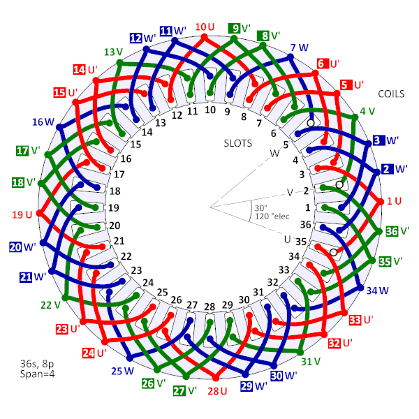
A typical 36-slot winding diagram will include the following information:
- Slot Numbering: Each slot in the stator is assigned a number.
- Coil Representation: Coils are depicted as rectangles or other shapes, indicating their position within the slots.
- Phase Identification: Each coil is labeled with its phase (A, B, or C) and connection sequence.
- Connection Points: The diagram shows how the coil ends are connected to form the complete winding circuit.
- Number of Turns: The diagram may specify the number of turns in each coil.
Pro Tip: Understanding the specific terminology used in a winding diagram is crucial. Familiarize yourself with terms like “start,” “finish,” “series,” and “parallel” connections.
Steps for Utilizing a 36-Slot Motor Winding Diagram
Once you have a winding diagram, the process of winding a 36-slot motor typically involves the following steps:
- Preparation: Gather the necessary materials, including the correct gauge of wire, insulating materials (slot liners, phase insulation), and tools like a coil winder and soldering equipment.
- Slot Lining: Insert slot liners into each slot to protect the windings from the stator core.
- Coil Winding: Carefully wind the coils according to the diagram, ensuring the correct number of turns and the correct pitch.
- Coil Insertion: Insert the wound coils into the stator slots, following the diagram’s instructions.
- Connection and Soldering: Connect the coil ends according to the diagram, soldering the connections securely.
- Insulation and Testing: Insulate the connected windings and test the completed winding for shorts, opens, and proper resistance.
Safety Note: Always disconnect the motor from the power supply before working on the windings. Use appropriate safety equipment, including gloves and eye protection.
Applications and Considerations
36-slot motors are commonly found in a variety of applications, including:
- Industrial Motors: Used in pumps, fans, and other industrial equipment.
- Servo Motors: Used in robotics and automation systems.
- HVAC Systems: Found in air conditioning and heating units.
- Hobby Projects: Often used in DIY projects and model making.
Important Considerations:
- Voltage and Current: The winding design must be appropriate for the intended voltage and current requirements.
- Motor Speed: The number of poles and winding configuration directly affect the motor’s speed.
- Efficiency: Proper winding design can optimize the motor’s efficiency.
- Thermal Management: Adequate insulation and ventilation are crucial to prevent overheating.
Troubleshooting and Repair
Understanding the winding diagram is critical for troubleshooting and repairing motor problems. Common issues include:
- Short Circuits: Wires touching each other or the stator core, leading to excessive current flow.
- Open Circuits: A broken wire within a winding, preventing current flow.
- Ground Faults: A wire touching the motor frame, causing a safety hazard.
Using the winding diagram, you can systematically test the windings for these faults and identify the source of the problem. Repairing damaged windings often involves removing the faulty coils, rewinding them, and reinserting them into the stator.
Conclusion
The 36-slot motor winding diagram is an indispensable tool for engineers and hobbyists working with electric motors. By understanding the fundamentals of winding diagrams and the winding process, you can design, build, maintain, and troubleshoot these critical components. Whether you’re a seasoned professional or a curious enthusiast, this guide provides the knowledge and insights you need to succeed in the world of electric motors. Mastering this skill empowers you to unlock the full potential of these fascinating and essential machines.
Frequently Asked Questions (FAQs)
1. What is the difference between lap and wave winding?
Lap winding typically involves coils that overlap, providing higher current capacity. Wave winding generally involves a different coil connection scheme, which might be more suitable for high-voltage, low-current applications.
2. How do I choose the correct wire gauge for my motor?
The wire gauge is determined by the motor’s current requirements. A larger wire gauge (lower AWG number) is needed for higher current applications to prevent overheating. Consult a wire gauge chart or use online calculators for proper sizing.
3. Can I rewind a motor with a different winding configuration?
Yes, but it requires a thorough understanding of motor design and the desired performance characteristics. Changing the winding configuration will alter the motor’s speed, torque, and current draw.
4. Where can I find a winding diagram for my specific motor?
Winding diagrams can often be found in motor service manuals, online databases, or by contacting the motor manufacturer. You may also find diagrams in related forums and communities.
5. What tools are essential for motor winding?
Essential tools include a coil winder, wire strippers, soldering iron, multimeter, slot liners, and insulating tape. A good quality set of hand tools is also helpful.
